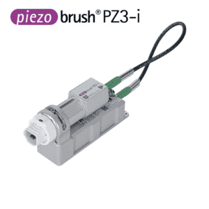
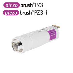
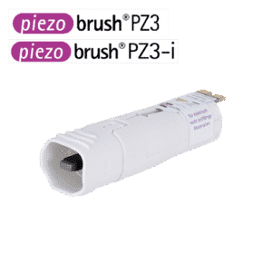
PiezoBrush PZ3-i
Compact plasma integration as industry standard of the future
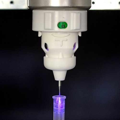
The PiezoBrush PZ3-i cold plasma device is designed for integration into new and existing production systems and is therefore compact, safe and efficient. The PiezoBrush PZ3-i is particularly suitable for the pretreatment of surfaces prior to subsequent processes such as bonding, printing and laminating, thus ensuring both process and product quality.
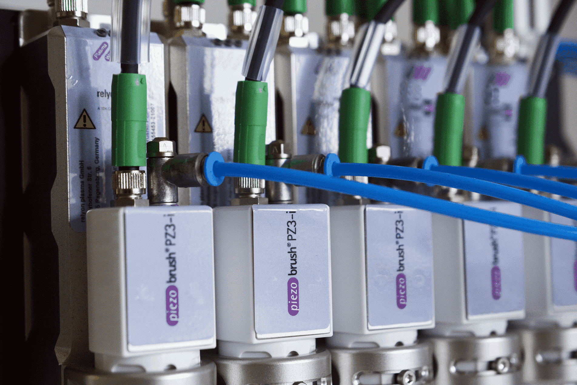
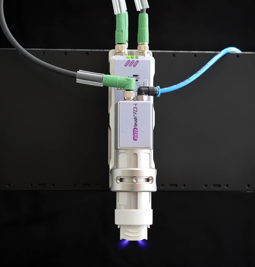
Due to its uniquely compact and robust design, the PiezoBrush PZ3-i can be quickly and easily integrated into production lines as well as partially to fully automated systems. In addition, comprehensive process control is possible in automated production processes, ensuring traceability. The device is also intuitive to operate and can be maintained without tools.
Applications
- Inkjet, marking and pad printing
- Bonding processes with epoxy, polyurethane and cyanoacrylates etc.
- Potting and dispensing technology
- Joining and assembly technology
- Laboratory and medical technology
- Packaging technology
- Microbiology, microfluid and food technology
Fields of application
- Activation of surfaces of a wide variety of base materials
- Optimization of bonding, printing and lamination processes
- Surface treatment of plastics, glasses, ceramics, metals, composites and natural materials
- Selective improvement of the wettability of a wide variety of surfaces
- Fine cleaning of surfaces
- Alternative to chemical primers, flame treatment processes and mechanical roughening
Application examples
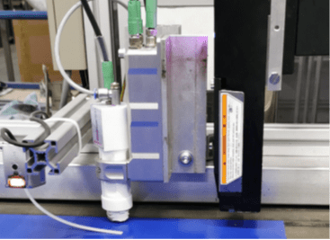
piezobrush® PZ3-i beta test report
A market-leading company in the development, production and distribution of surface treatment tooling solutions uses the new piezobrush® PZ3-i in conjunction with the KEYENCE MK-G1000SA continuous inkjet printer to safely and effectively mark PTFE fabrics.
PiezoBrush PZ3-i in our Online Shop
-
PiezoBrush PZ3-i with CAN-bus interface (without modules)3.280,00 €
excl. 19% VAT
-
PiezoBrush PZ3-i without CAN-bus interface (without modules)3.050,00 €
excl. 19% VAT
-
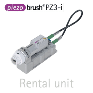
Rental unit PiezoBrush PZ3-i550,00 € / 15 days
excl. 19% VAT
Technical data PiezoBrush PZ3-i
- Electrical connection: 24 V DC
- Power consumption: max. 18 W
- Weight: 370 g
- Design: Integration unit with gas connection
- Plasma temperature: < 50 °C
- Typical treatment speeds:
- Finest cleaning: 1-15 mm/s
- Bonding processes: 10-150 mm/s
- Printing processes: 100-1500 mm/s
- Typical treatment distance: 2 – 10 mm
- Typical treatment width: 5 – 29 mm
Modularity
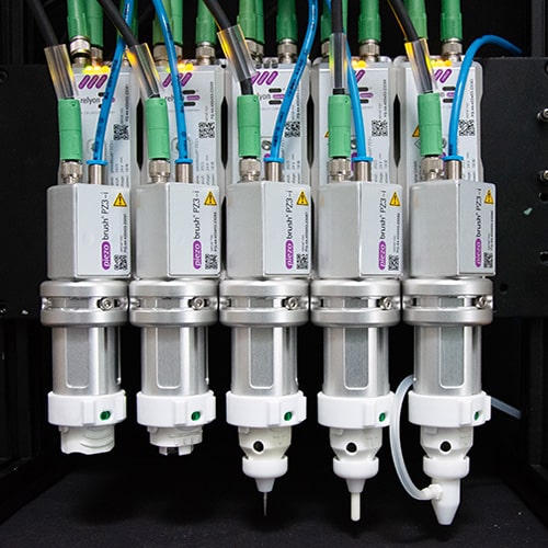
With an average treatment width of 5 – 29 mm (CDA), the PiezoBrush PZ3-i is very well suited for the pre-treatment of adhesive grooves or for marking printing on low-energy materials. However, with other process gases such as nitrogen, even treatment widths of up to 50 mm are possible. For many applications, however, even larger treatment widths are required. Thanks to the modular design, it is very easy to string together the individual units at any time, so that even larger treatment widths can be individually adapted to the application.
Modules
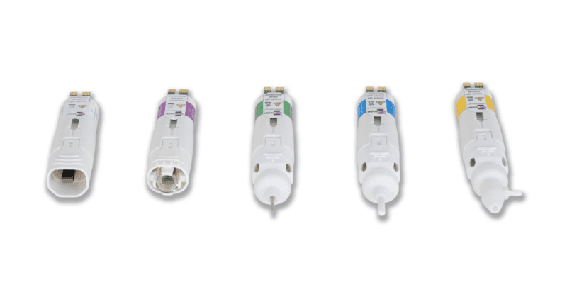
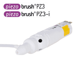
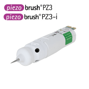
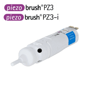
Different surfaces have to be activated with the appropriate accessories to achieve an ideal result. Currently five different modules are available for the PiezoBrush PZ3-i plasma integration unit. The PDD technology used to generate the cold plasma in PiezoBrush PZ3-i is based on the discharge of high electric fields. Therefore, the electrical conductivity of the component to be treated is of decisive importance when choosing the modules.
Modules in our Online Shop
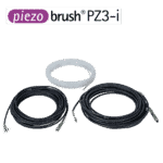
Connection cables for PiezoBrush PZ3-i
This optional accessory set for the PiezoBrush PZ3-i consists of a DC connection cable, a communication connection cable and a gas hose. Each cable is 10 m long. The accessory set is available in the onlineshop.
Advantages
- Ease of maintenance: module change without tools, basically rarely maintenance required
- Modularity: modules matched to the application and substrate material, multiple units can be connected in series
- Communication and process safety: monitoring by plasma OK signal whether module is in permissible operating point, extremely low temperature input on the materials (no thermal overtreatment of substrates possible), digital I/O signal, LED status display, low flow velocities for temperature-sensitive materials and lightweight components, optional: BUS communication available (module history can be read out)
- Work safety: touch safety (no light barrier or mechanical enclosure required), generally no personal protective equipment (PPE) necessary, very low nitrogen oxides
- Integration: power supply by low voltage (24 V), low weight enables low-cost robot units, easy to integrate, compact design (separability of module carrier and driver unit), also suitable for small installation space, easy to implement hardware interfaces
- Environmental friendliness: energy efficiency (max. 18 W), very low consumption of process gases (10 l/min), very environmentally harmful processes such as chemical primer or flame treatment processes are replaced
- Very good price-performance ratio: low operating costs, customer-friendly initial costs
- Low-threshold process validation due to compatibility with handheld device: identical core components and performance class
FAQ
Downloads
| Description | Language | Download |
|---|---|---|
| Manual PiezoBrush PZ3-i | EN/DE | Manual in English and German |
| Manual PiezoBrush PZ3-i | FR | Manual in French |
| Manual PiezoBrush PZ3-i | ES | Manual in Spanish |
| Manual PiezoBrush PZ3-i | IT | Manual in Italian |
| Manual PiezoBrush PZ3-i | CN | Manual in Chinese |
| Manual PiezoBrush PZ3-i | JP | Manual in Japanese |
| Documents for PiezoBrush PZ3-i CAN Integration (EDS file, Device Document) | EN | Documents for CAN Integration |
| Flyer PiezoBrush PZ3-i | EN | Flyer |
| Comparison PiezoBrush PZ2-i and PiezoBrush PZ3-i | EN | Flyer |
| Press release PiezoBrush PZ3-i | FR | Press release |
| Paper: Application of Nitrogen Piezoelectric Direct Discharge | EN | Paper |
| Whitepaper PiezoBrush PZ3: endurance test for standard module | EN | Whitepaper |


