
Thermographic investigations on the pretreatment of polypropylene
Motivation and objective
As part of the beta test campaign for the piezobrush® PZ3 device from relyon plasma GmbH, the SKZ conducted investigations on the adhesion enhancement of a 2C epoxy adhesive on a low-energy and thus difficult-to-bond plastic polypropylene (PP). In addition to the piezobrush® PZ3 and the predecessor model PZ2 (both based on “piezoelectric direct discharge” (PDD) plasma technology), a conventional atmospheric pressure plasma system with rotating nozzle (ADP) was used. Furthermore, the plasma pretreatment process was monitored by thermography to investigate the influence of the pretreatment type on the temperature rise of the substrate.
Materials and methods
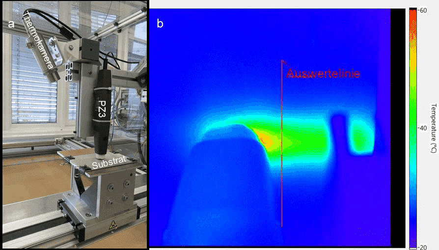
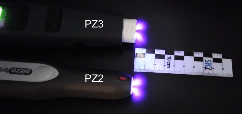
Extruded PP sheets (MEPOLEN PP-H, BEN Kunststoffe Vertriebs-GmbH) with a thickness of 2 mm were used as substrates. After cleaning the PP substrates in an ultrasonic bath for 5 min and subsequent airing for 15 min in an automated pretreatment stand with integrated motorized axes, the plates were pretreated with the three different devices (PZ2, PZ3 and ADP) (cf. Figure 1a). A thermal camera from Optris GmbH with a frame rate of 80 Hz, which was also installed, recorded thermograms during pretreatment, which were evaluated with respect to their temperature distribution via a line profile (red line) 2.0 cm away (cf. Figure 1b). Both the thermal camera and the individual pretreatment units were permanently installed, and the defined treatment speed was realized using the axis-controlled sample table method. The treatment distance between the substrate and the two piezobrush units was chosen based on the recommendations of the unit manufacturer, which were 3.0 mm, 6.0 mm and 9.0 mm. Figure 2 shows the optically detectable plasma exit area. It can be clearly seen here that the active area of the plasma protrudes approximately 12 mm from the nozzle opening on both devices. For the ADP, the nozzle spacing was 8.0 mm. The treatment speeds varied between 0.5 mm/s and 20.0 mm/s.
In order to determine suitable pretreatment parameters for the adhesion tests, contact angle measurements were carried out to determine the surface free energy (SFE) on the pretreated substrates according to DIN EN ISO 19403-2 using a Drop Shape Analyzer DSA30 from KRÜSS GmbH. The test liquids used were
Diiodomethane and deionized water (both p.a. purity) were used as test liquids. Five droplets per test liquid were deposited during each measurement. The evaluation of the measurement data was performed according to the Owens-Wendt-Rabel-Kaelble method (OWRK). The most promising pretreatment parameters in terms of their SFE were then used for the strength tests.
Tensile tests were carried out using the LUMiFrac adhesion analyzer from LUM GmbH based on CAT technology. The adhesive used was the 2C epoxy adhesive DELO-DUOPOX® AD840 from DELO Industrie Klebstoffe GmbH & Co. KGaA was used. The bonds were produced between the plastic specimen and a metal adapter. For this purpose, the stainless steel screw-in adapter V2A-D10 with a diameter of 10.0 mm was previously ground and cleaned with isopropanol. Before applying the adhesive, approx. 5 to 20 glass beads (Ø = 80 to 100 μm) were placed on the joining surface to ensure a constant adhesive layer thickness. A sufficient amount of adhesive was then applied so that the entire bonding surface could be filled by increasing the contact pressure, but the adhesive did not flow out several millimeters laterally. Six tensile test specimens were made for each specimen-adhesive combination. Curing took place at a constant contact pressure of 1.0 N under standard climate conditions (23 °C, 50 % humidity) for seven days.
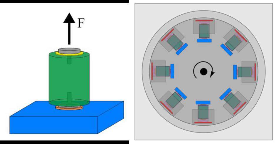
Figure 3 on the left shows the schematic structure of the specimen for the tensile test. The stainless steel screw-in adapter (gray) and a copper weight (green) are connected to the plastic (blue) via an adhesive layer (orange). The test setup is shown in Figure 3 on the right. For testing, the assembly is rota-ted so that the centrifugal force on the test plunger is increased at 5.0 N/s. If the test punch breaks at a certain load, a sensor (red) detects the impact. The tensile strength can then be determined via the speed at impact and fracture surface. The fracture type of the LUMiFrac specimens was then classified according to DIN EN ISO 10365.
Contact angle measurements
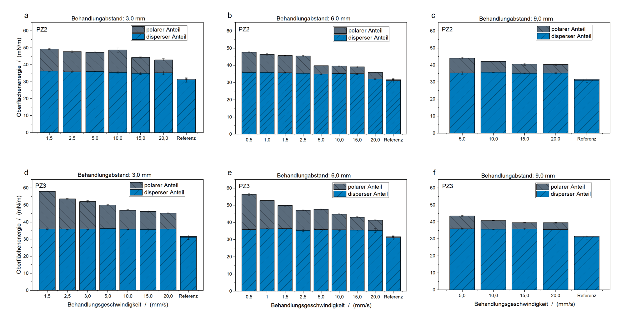
Looking at the results of the contact angle measurements in Figure 4, it can be clearly seen that the SFE of the PP substrate increases after pretreatment with the PZ2 (a – c) and the PZ3 (d – f) as a function of the treatment distance (a, d: 3.0 mm; b, e: 6.0 mm; c, f: 9.0 mm) compared to the untreated condition (reference). While the PP reference has a SFE of 31.7 mN/m with hardly any polar component (0.6 mN/m), the SFE increases continuously with decreasing treatment distance and lower treatment speed. A steady increase in the polar fraction can be observed, with the disperse fraction remaining at a constant level (about 35 mN/m). When comparing the PZ2 with the PZ3, it is noticeable that higher values for the SFE of the substrate are achieved with the PZ3 at the same treatment distance and speed. While it was not possible to achieve an SFE of more than 50 mN/m with the PZ2 for the selected parameters, an increase in the SFE to almost 60 mN/m was recorded with the PZ3. It is also noticeable that pretreatment at a treatment distance of 9.0 mm results in only a slight increase in the SFE of the substrate, irrespective of the version of the piezobrush. Although the active plasma region extends about 12 mm out from the plasma nozzle in both devices as shown in Figure 2, the decreasing energy input into the substrate with increasing distance seems to be the reason for the lower surface activation. In addition, the low standard deviations of the determined SFE indicate a homogeneous pretreatment with the piezobrush devices. An improvement in the wettability of the PP substrate could thus be achieved by means of PDD plasma.
Tensile tests using LUMiFrac
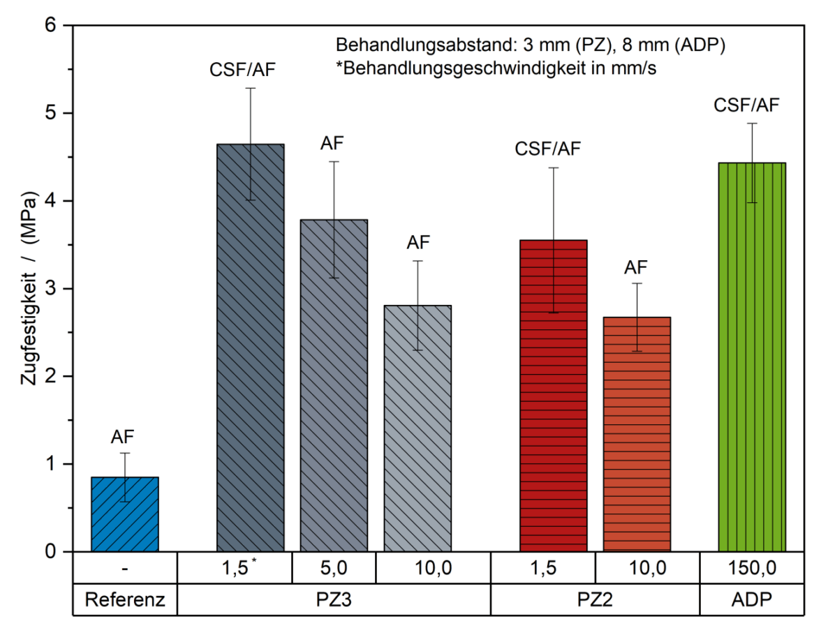
In order to investigate the influence of the substrate pretreatment on the bond strength, bondings were carried out on selected treatment parameters. In addition to reference samples (untreated PP), samples were also pretreated with the PZ2 and PZ3 at a treatment distance of 3.0 mm, since the greatest increase in SFE values was achieved here compared to the untreated reference. The treatment speeds selected were 1.5 mm/s and 10.0 mm/s for PZ2 and 1.5 mm/s, 5.0 mm/s and 10.0 mm/s for PZ3. In addition, a conventional atmospheric pressure plasma system with a rotary nozzle served as a comparison method. The parameters selected here (treatment distance: 8.0 mm or treatment speed: 150.0 mm/s) for optimum bond strength resulted from preliminary tests with the PP substrate and adhesive used.
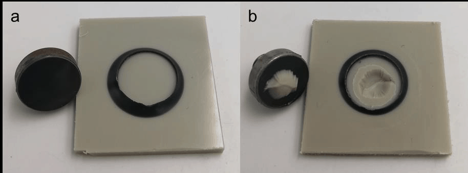
The results of the tensile strength tests using Adhesion Analyzer are shown in Figure 5. It can be clearly seen that with all pretreatment methods a significant increase in bond strength is achieved compared to the untreated PP. With a PZ3 pretreatment at a treatment speed of 1.5 mm/s, the tensile strength of the bonded joint can even be increased from about 1.0 MPa in the base state to up to 4.5 MPa after pretreatment. There is also a change in the fracture pattern: while the reference specimens show an adhesive failure (AF), a partially cohesive joint failure (CSF) occurs after the pretreatment described (cf. Figure 6). Furthermore, it is noticeable that the bond strength increases with decreasing treatment speed for PZ2 and PZ3 and that the fracture pattern changes from AF to CSF.
In addition, the results suggest an increased bond strength at the same treatment speed (1.5 mm/s) by using PZ3 compared to PZ2. Thus, for the selected adhesive-substrate combination, a correlation can be made between the increased SFE after pretreatment and the improved bond strength. When comparing the PDD plasma technology with a conventional ADP from a rotary nozzle, an equivalent increase in bond strength can be achieved with optimum parameter selection.
Thermography during pre-treatment
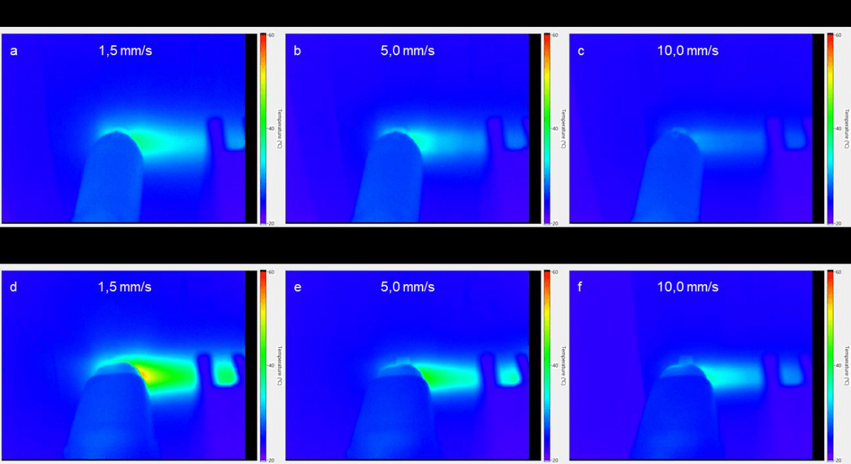
In order to investigate how much the temperature change on the PP substrates is during the pretreatment with the PZ2 and PZ3, the process was monitored with a thermocamera. Figure 7 shows three thermograms each at treatment speeds of 1.5 mm/s, 5.0 mm/s and 10.0 mm/s during the pre-treatment process with the PZ2 (a – c) and PZ3 (d – f). The treatment distance was set to a constant 3.0 mm here. Looking at the thermograms, it is noticeable that the temperature load decreases with increasing treatment speed, as expected. It can also be seen that pre-treatment with PZ3 causes a greater temperature increase at the same treatment speed than its predecessor PZ2. Nevertheless, the surface temperatures of the substrate remain below 55 °C even at very slow treatment speeds (e.g. 1.5 mm/s).
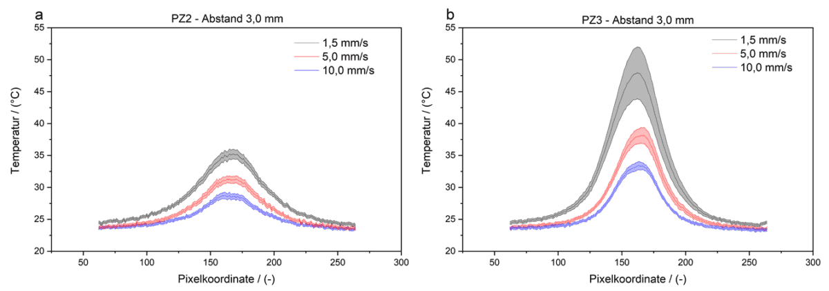
This is again illustrated in the graphical plot of temperature versus pixel coordinate along the evaluation line in Figure 8. While the maximum temperature for treatment with the PZ2 does not exceed 35 °C, a treatment speed of 1.5 mm/s with the PZ3 results in a maximum temperature of approx. 53 °C. However, at the treatment speeds of 10.0 to 20.0 mm/s recommended by the manufacturer, no temperatures above 35 °C can be detected even with the PZ3.
Conclusion
In summary, it can be said that surface modification by means of PDD technology of the non-polar plastic PP is very possible. By pretreating PP with the PZ2 or PZ3, the surface energy (especially the polar fraction) can be increased when suitable treatment parameters are selected, and a significant increase in adhesive strength can be achieved compared to the untreated PP substrate. It could also be shown for the selected adhesive-substrate combination that a pretreatment with the PZ3 achieved a comparable strength increase as a pretreatment with a conventional ADP system with rotating nozzle at a higher treatment speed.
Another advantage of the PDD technology is the treatment of the substrate with cold-active plasma. Thermographic images showed that the temperature of the substrate did not rise above 55 °C even at low treatment speeds and short distances. This is particularly crucial for temperature-sensitive materials such as plastics. Thus, even films can be pretreated with the piezobrush devices without any problems and without damage. A disadvantage is the need for a lower treatment speed due to the lower power of the devices compared to conventional atmospheric plasma systems.
Furthermore, it could be shown by means of thermography that treatment with the PZ3 is somewhat more energy-intensive compared to the PZ2, but in return achieves a significant increase in SFE and adhesive strength compared to its predecessor version PZ2.